To learn more about digital electronics I built a random number generator. This project taught me how to solder and how different components work together to create a circuit board. I practiced soldering IC chips, resistors, LEDs, a button, and a capacitor on to the board.
I learned from several mistakes when first learning how to soldering. I found that tinning the surface before soldering made it much easier to bond the metals together. When using a soldering iron it is necessary to create a balance between the right amount of solder and time. I found that I was melting the board because I was too slow. Sadly the first time I put together the board it did not work. Having learned how to use a digital multi meter I determined that one of the IC chips were unresponsive. I must have melted the component due to excessive heat.
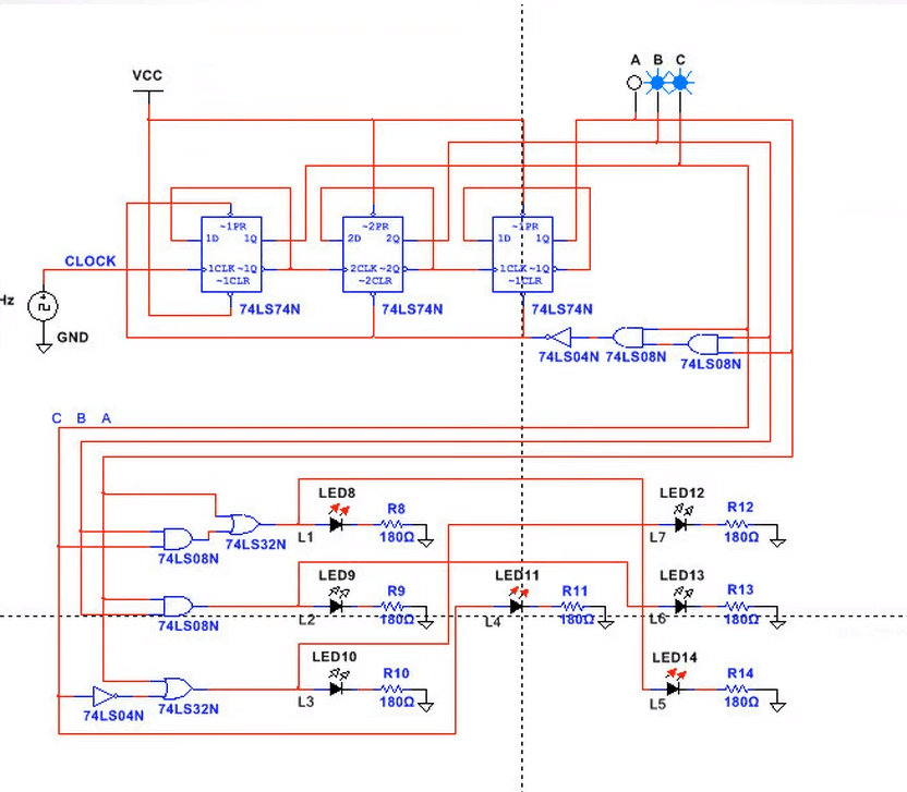
The basic principles of the board consists of a button that closes the circuit and constantly charges a capacitor. The electricity then moves to the sequential logic section of the board. Sequential logic is in charge of creating a counter that allows for a random number between 1-6 to be chosen. Taking the digital signal created and outputting it as a binary number. The combinational logic of the board consists of and gates, or gates, invertors, resistors, and LEDs. Those components are in charge of taking the binary output of the sequential logic and supplying power to the corresponding LED.
 Andrew Stack