
At a Design Within Reach store in Chicago I came across a lamp designed by Michael Anastassiades. The retail value for the lamp was $700 a little too much for a student to purchase. I felt that recreating this lamp was the perfect challenge using an Arduino, 3D printed parts, copper tubing and a LED light strip.
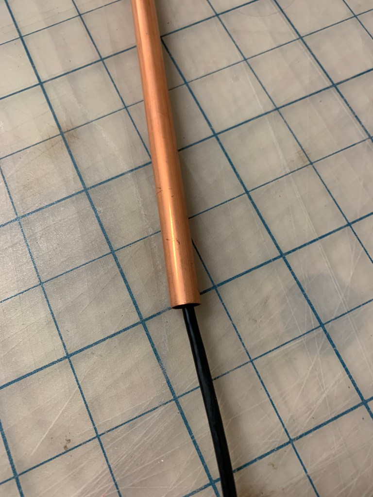
I needed to choose a material for the rods that would create the profile of the lamp. Originally I was planning to use aluminum. After seeing my options in person I decided to use copper. Not having access to power tools I felt that it would be too difficult to make a clean straight cut with the aluminum because it had a thicker shell. A draw back of copper is that its very soft and easy to bend. I purchased two two feet rods. The copper rod had a shell of .01″ with a diameter of 3/8″.
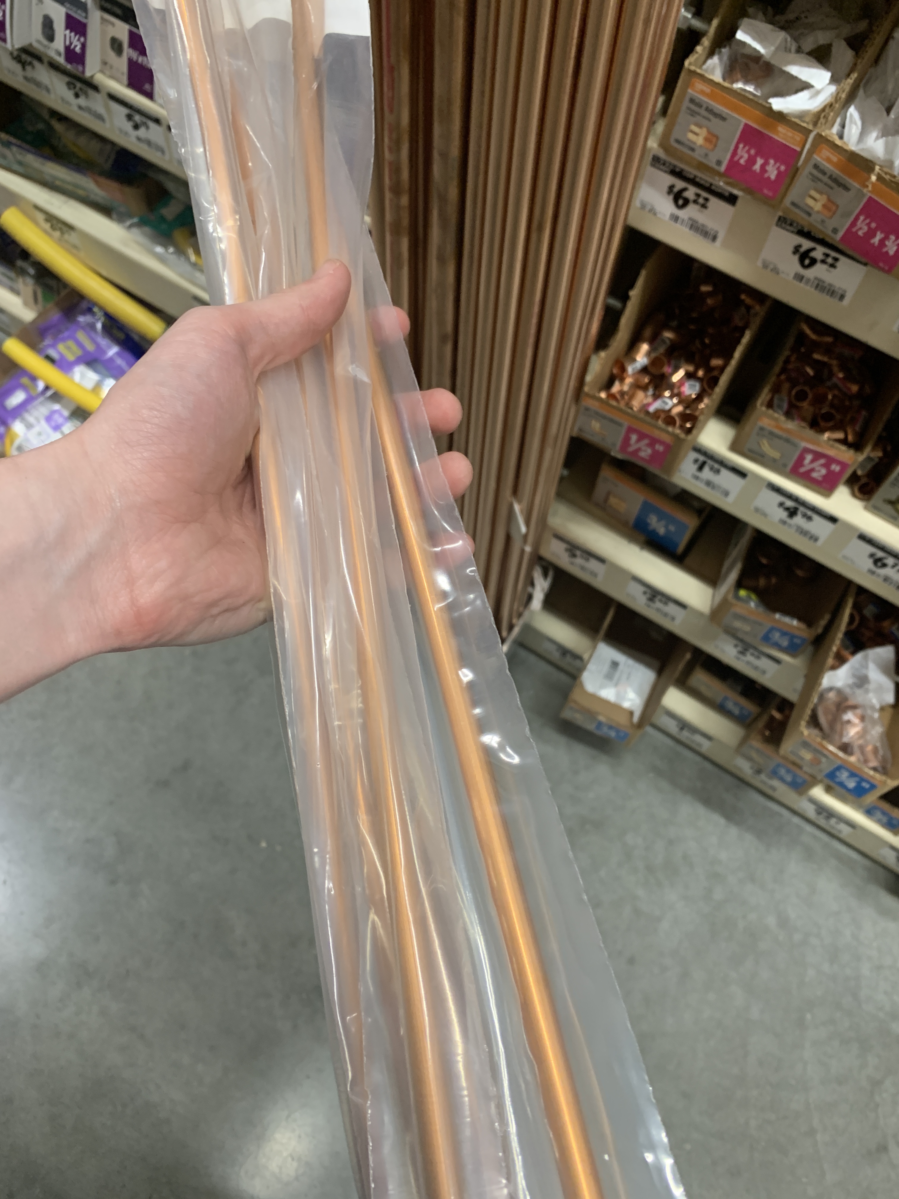
(Copper Tubing) 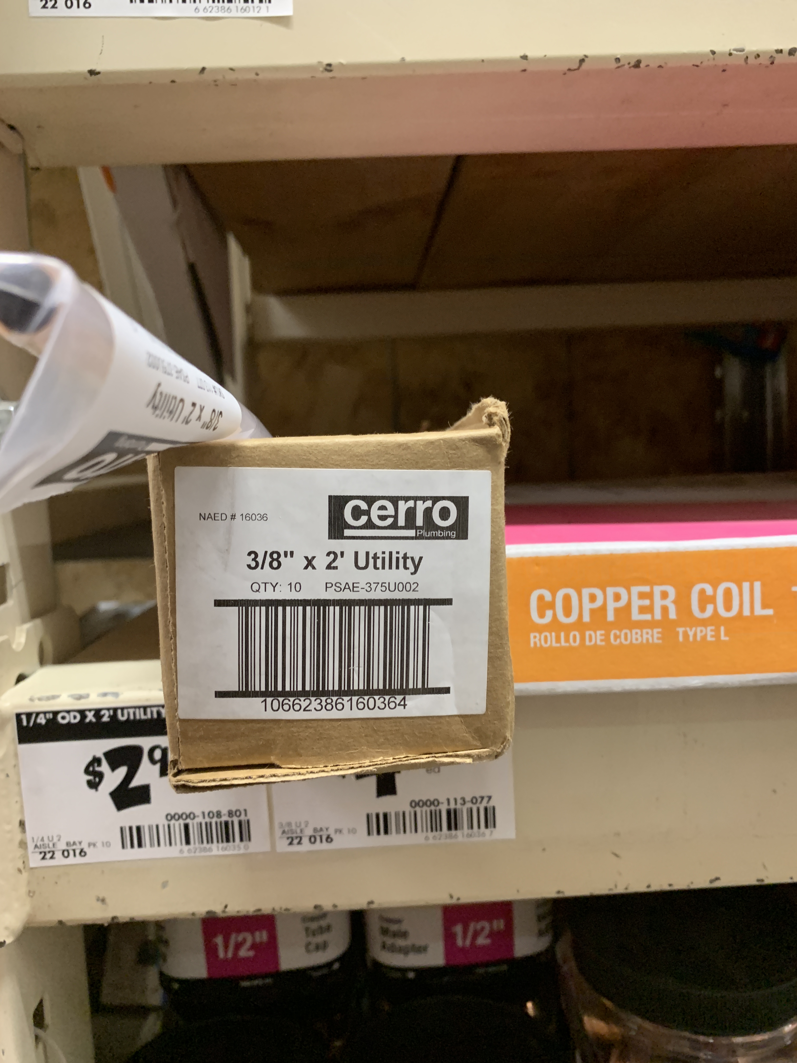
(3/8″ x 2′ Copper Spec)
In my basement I had found a miter box kit that would work to cut the tubbing in a straight line.
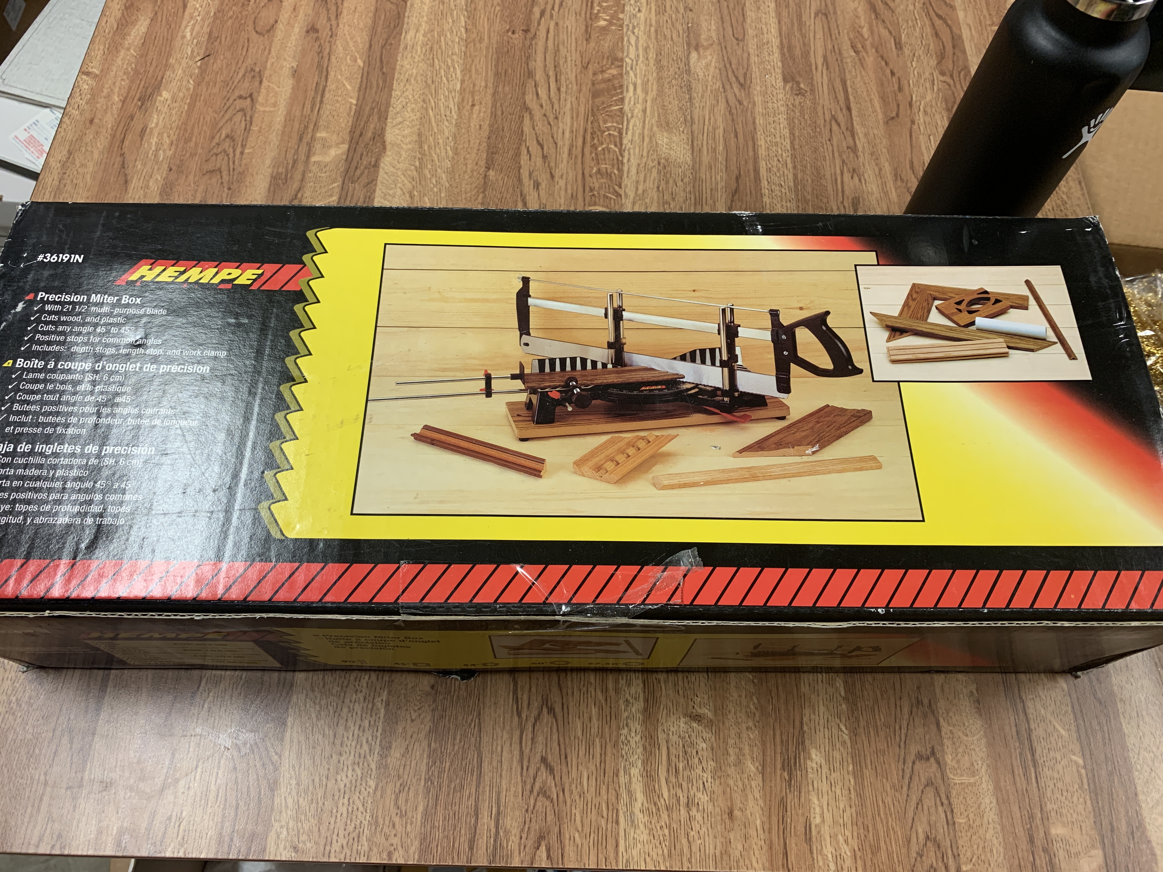
(Miter Saw Box) 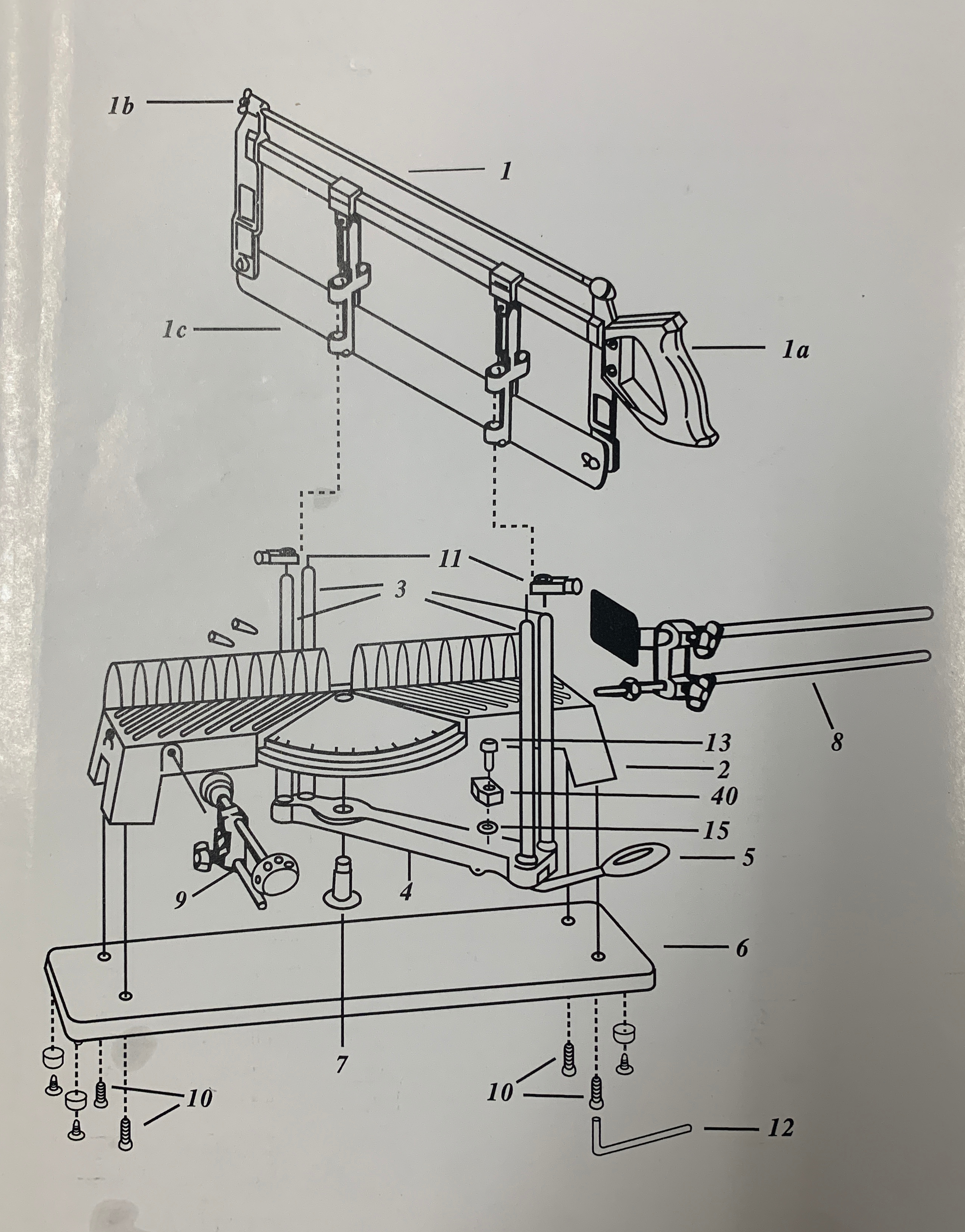
(Miter Saw Instructions) 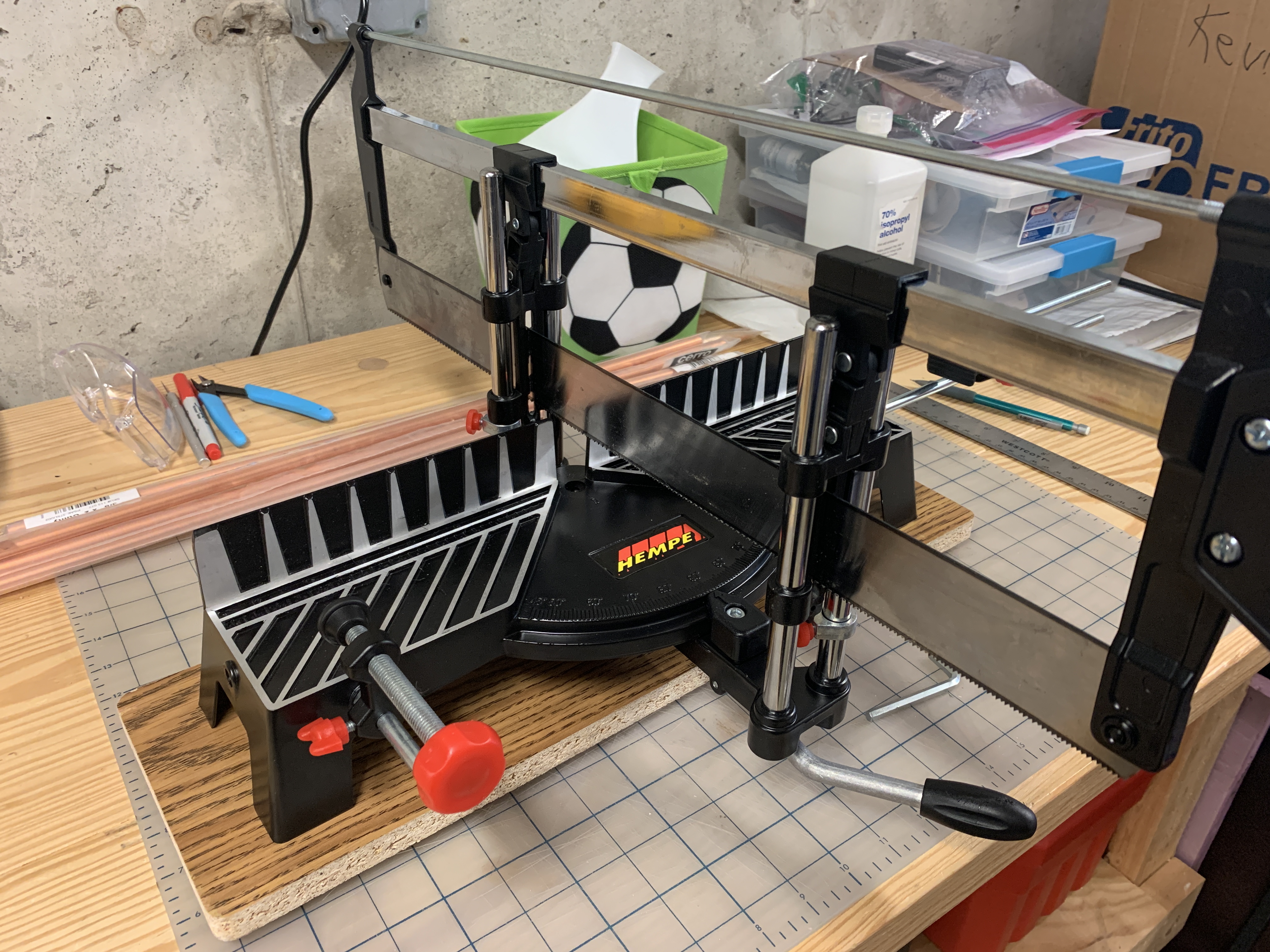
(Miter Saw Complete)
After assembling the miter saw kit I began cutting the first copper rod. The miter kit was not doing a very good job at making a clean cut. The heavy force of the blade was disfiguring the soft copper rod. So I finished cutting the rest of the rods with a hand saw.

(Placed Against Stop Block) 
(Miter Saw Cut) 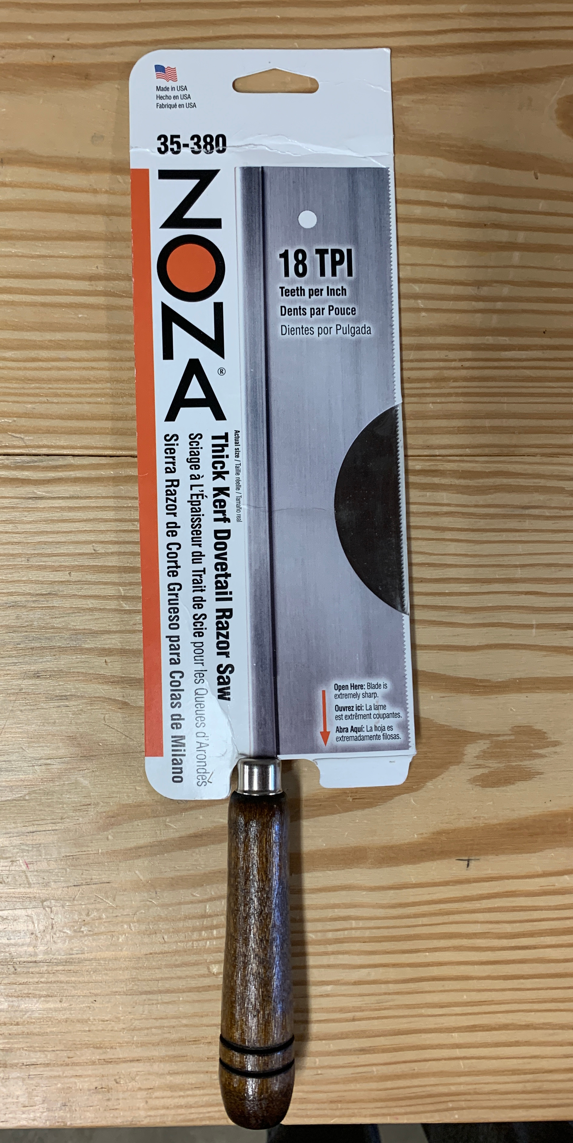
(Hand Held Saw)
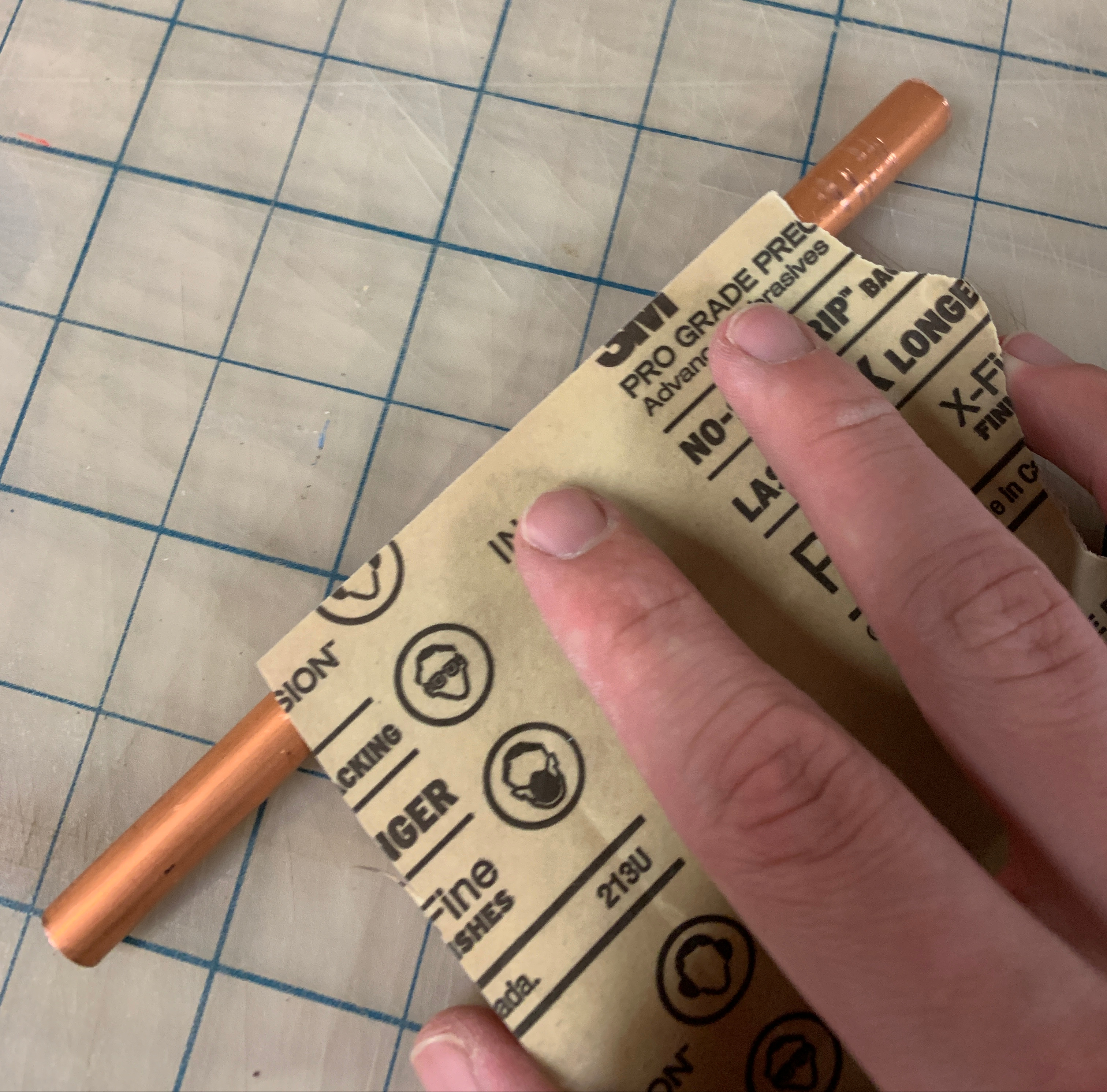
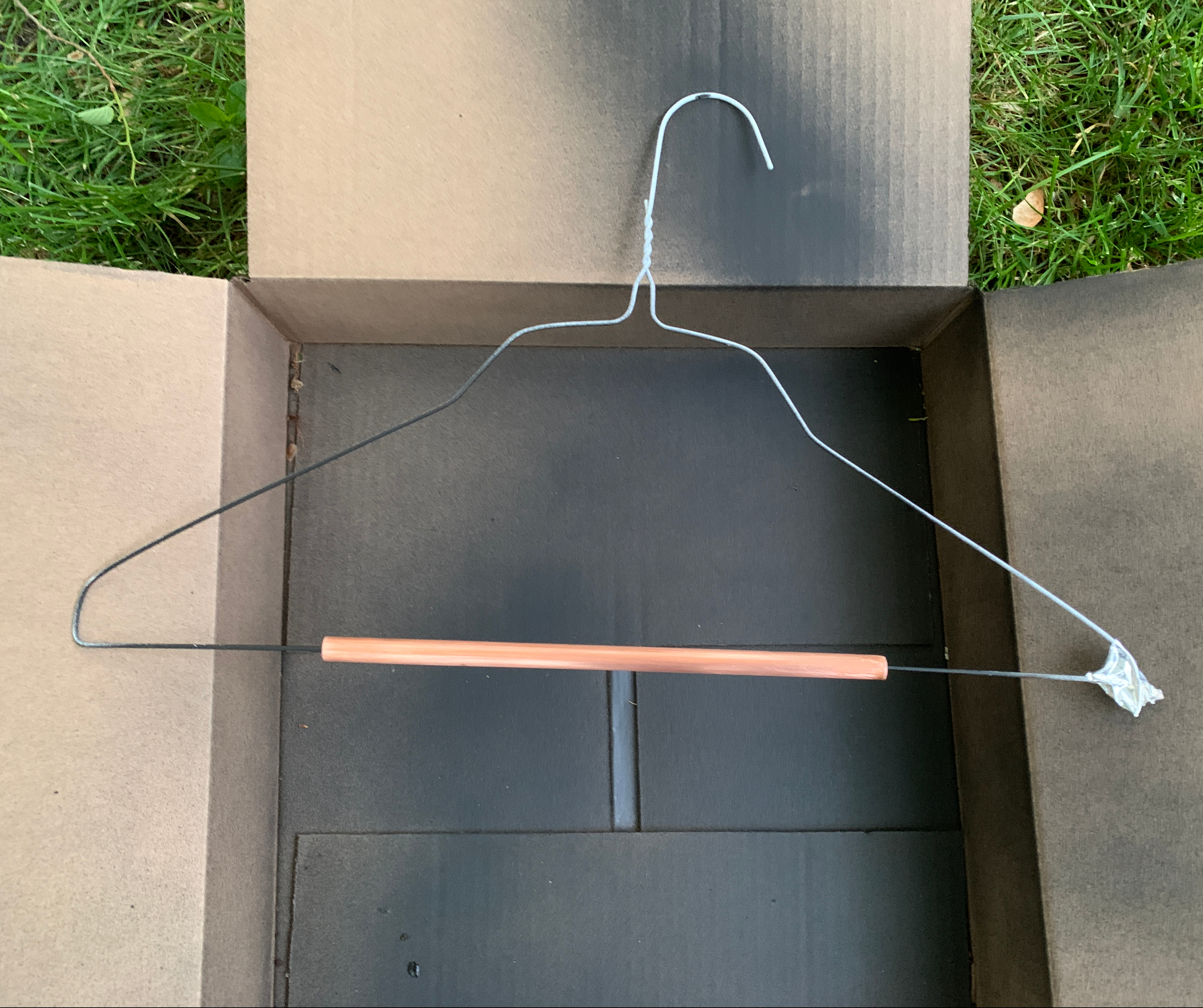
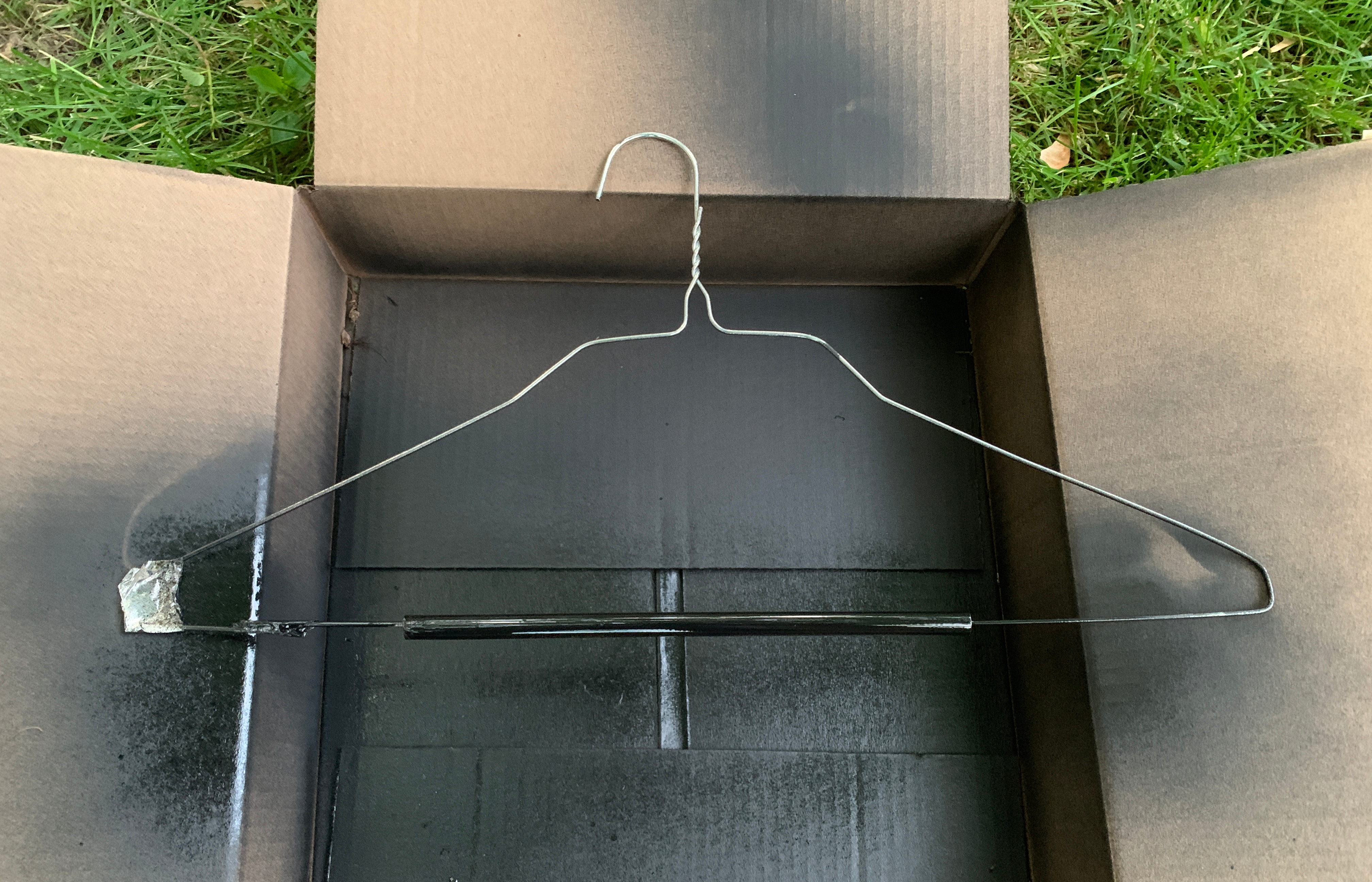
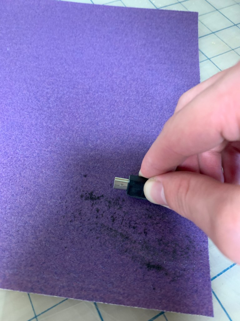
After I finished cutting all of the rods I spray painted it matte black. I lightly sanded the copper to ensure the paint would adhere to the copper getting rid of the shinny scheme. I originally tried to make a spray booth by stringing thread through a small hole I drilled through the top of the copper rod. This proved to be tedious and I came up with idea to string the rods through clothing hangers. This allowed me to easily rotate the rods to ensure I had ample coverage. Once all of the rods were painted I moved onto the electronics and 3D printing the joints.






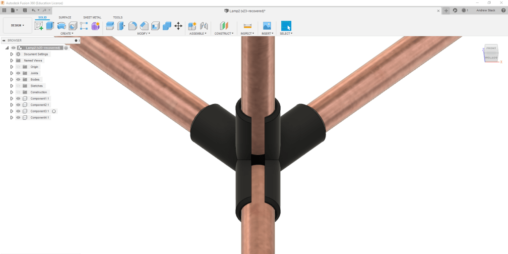
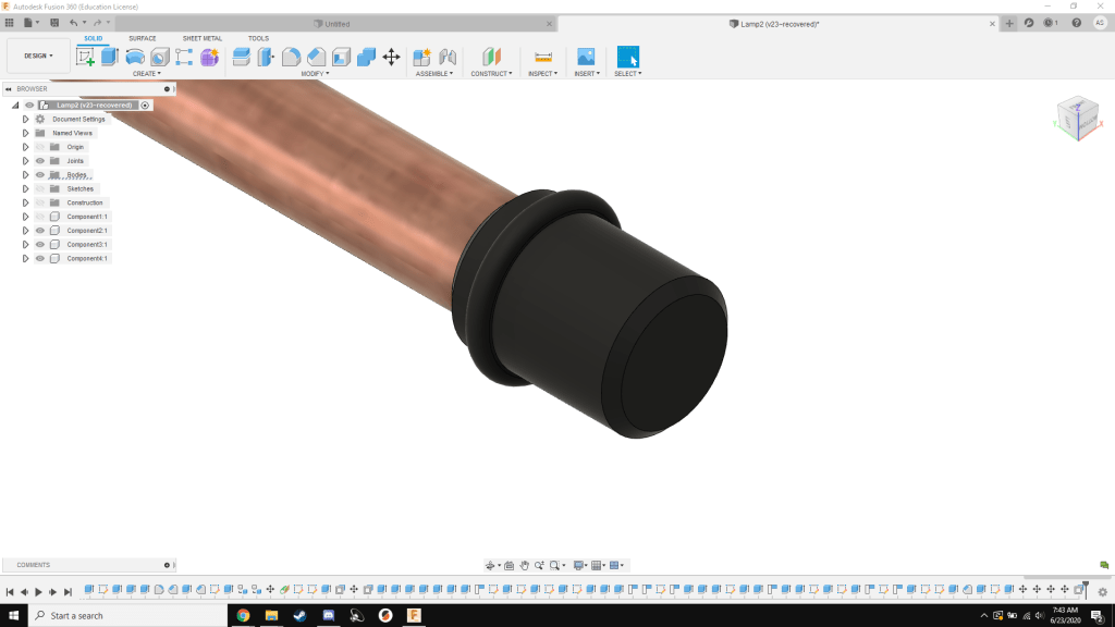
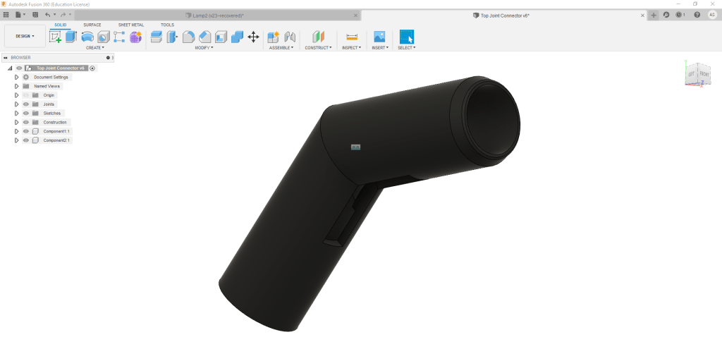
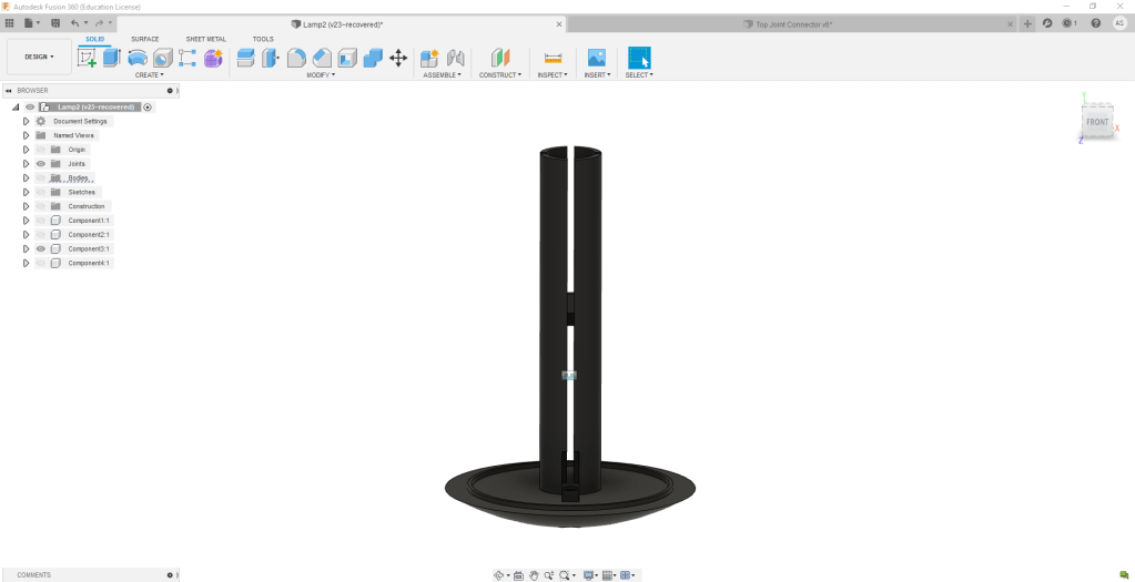
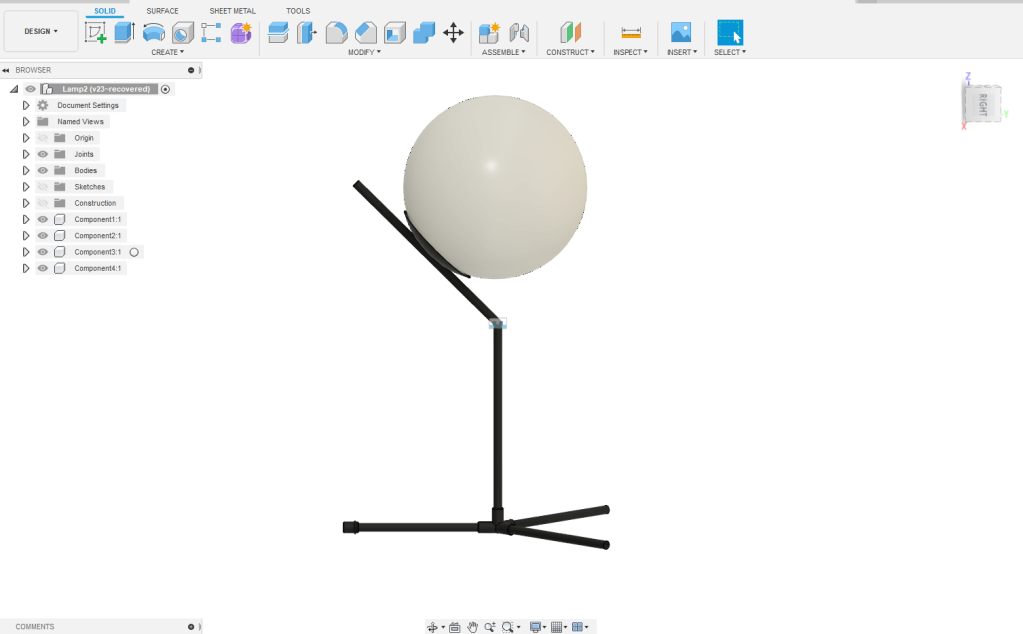
I based my designs based off of the dimensions online. Using my 3D model this determined the length at which I needed to cut the rods and the size of my connector joints. I designed the bottom connector joint to connect the tri shaped rods. In addition the electronics housing unit housing the LED light strip and Arduino. This would be screwed into the top rod. The white globe would secure to the electronics housing as a pressure fit. I felt that this was ample due to the angle that it would rest at.


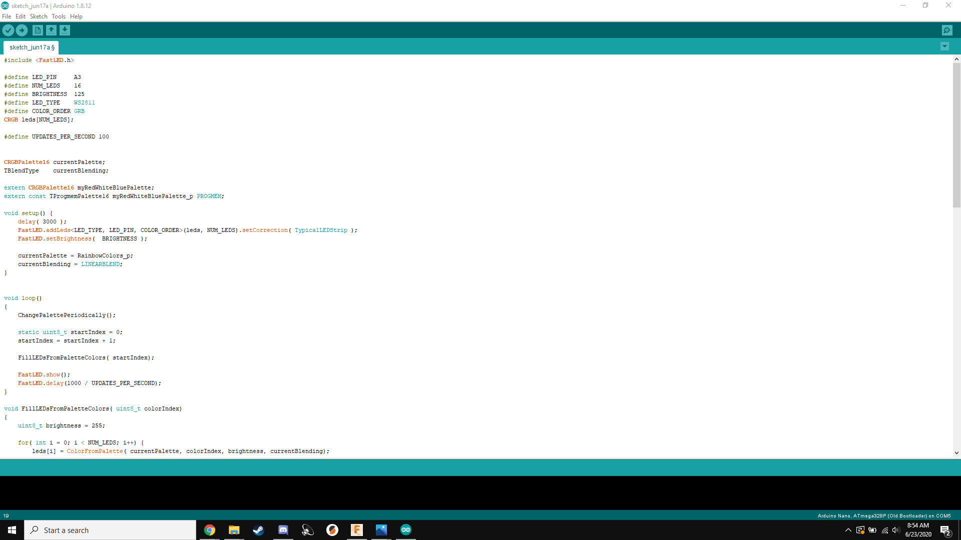
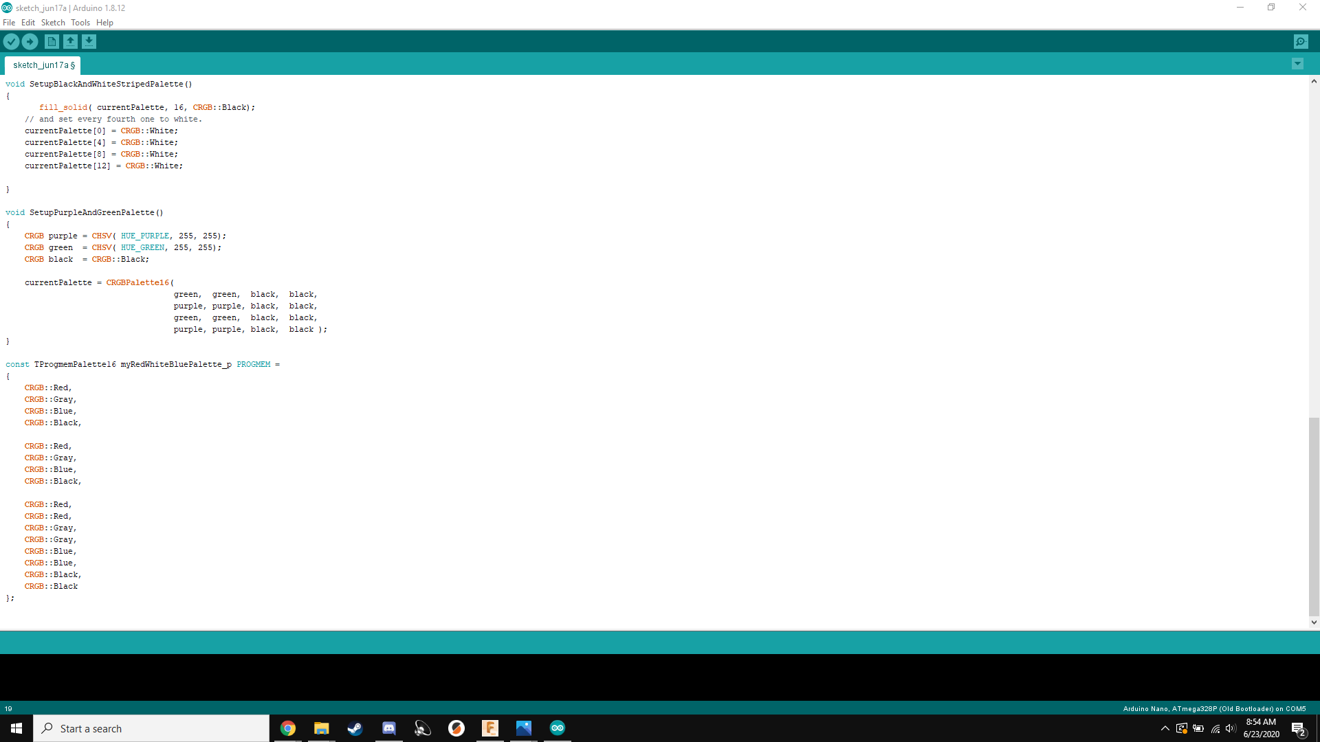
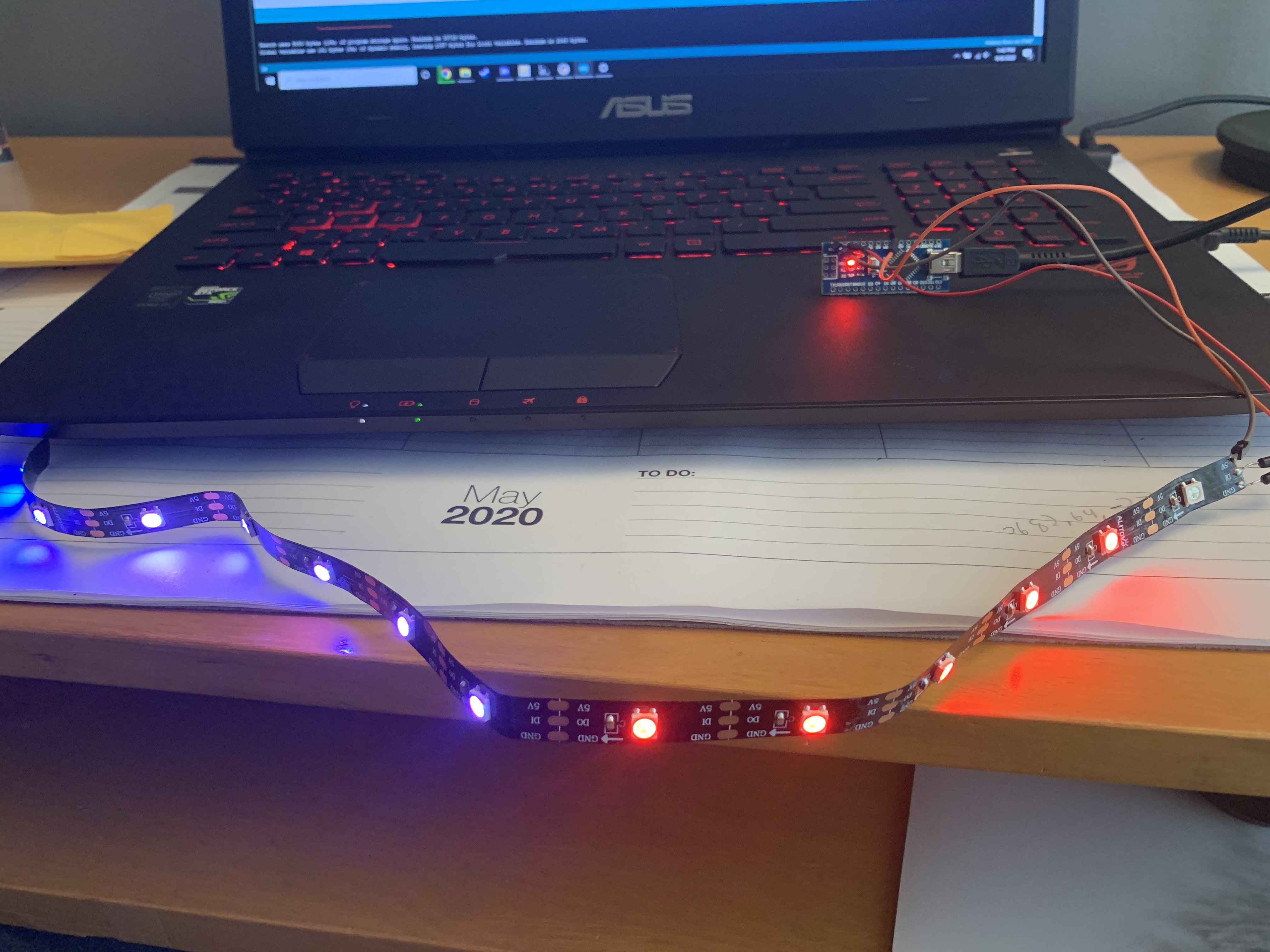
The next step was to program the LED strip. I purchased an Arduino Nano on Amazon and used the Fast LED library in Arduino IDE. I created several palates of colors for the Arduino to cycle through. I ran into some issues using the cheap knockoffs having to use the old Arduino processor (Old Bootloader). Once uploading my code I could test to see if it would work!
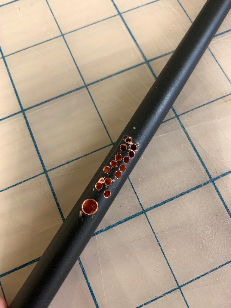
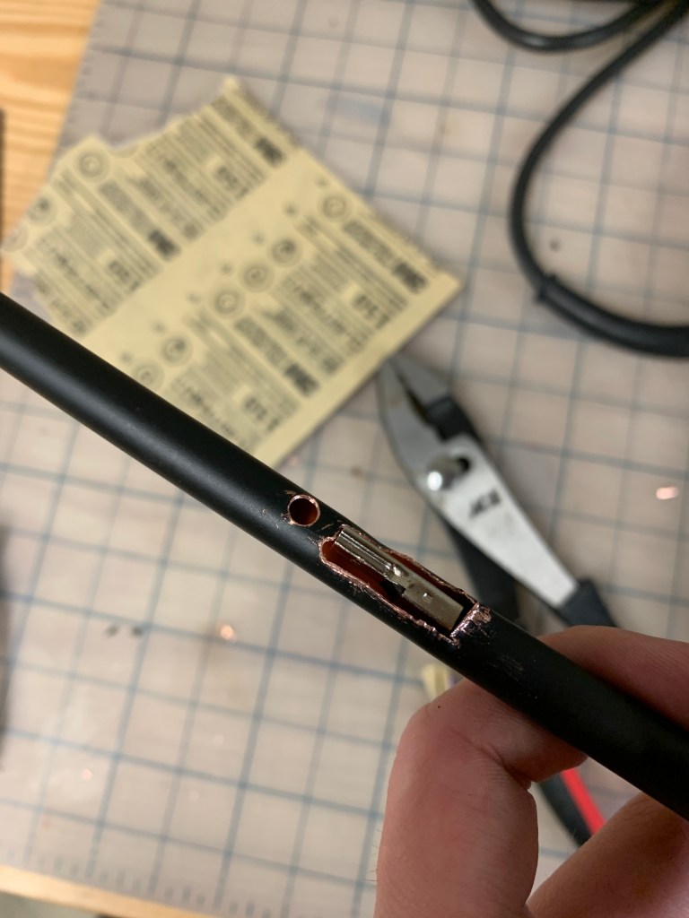
The next step of the process was to finish the rod post processing, gluing everything together and soldering the electronics. I needed to drill a hole into the copper rod to secure the electronics housing unit. Then cut out a square to slide the USB Mini through the rod to connect to the Arduino. To prevent tear out I drilled a small hole and then worked my way up to a 5/16″ drill bit for the securing hole. For the square I drilled several small holes and then used a small cutter to cut the material that was between the small gaps. This method worked very well.


To glue the rod to the connector joints I used Gorilla Epoxy. The epoxy dries very fast and creates a very strong bond.


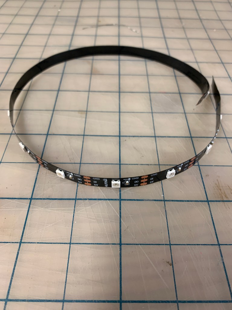
I then soldered the Arduino to the LED strip. The LED strip was requires GRND, PWR, and the DATA pin to be soldered. I hot glued everything to the electronics housing unit.


The last step was to secure the globe to the electronics together and test it out! It worked very well but the 3d printer left a line due to the angle of the globe.


 Andrew Stack